Codes and descriptions of connection faces
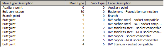
In the Project Environment dialog, in [library] > Configuration > Common, the Codes and descriptions of connection faces configuration object allows the project administrator to specify codes that designate the main type and subtype for connection faces. Accordingly, all connection points of a part are assigned codes that define their primary type and subtype. In this documentation, the connection types are referred to by their symbolic names instead of codes.
The main types are predefined—their meaning cannot be changed. The subtypes are numbered 0–200, meaning there can be 201 subtypes per main type.
All the necessary main types are included for object types Equipment, Standard Component, Piping Part, Beam, HVAC Part, Cable Tray, Cable Network Part, and Cable. Subtypes are defined to enable compatibility checks between connections. If two connections of the same size have different compatibility with another connection, they should have different subtypes to allow proper compatibility checking.
For this reason, flanged and wafer connection types are divided into different subtypes according to flange face ratings and shapes. In some cases, division is also based on nominal sizes when certain nominal sizes of two different ratings are compatible, but others are not. Welded main types are divided according to material groups to enable compatibility checks between them. If welded connections are always limited to components of one specification and those components are always compatible, then this division by material groups is unnecessary.
Joint materials for flanged and wafer-type connections (bolt sets and gaskets) and gaskets for clamp-type connections are defined in the piping specification according to the connection face types of the connected items.